Explore the three technical figures supplied for the FeBTUcell 2.0 concept.
Technical figures
01–03
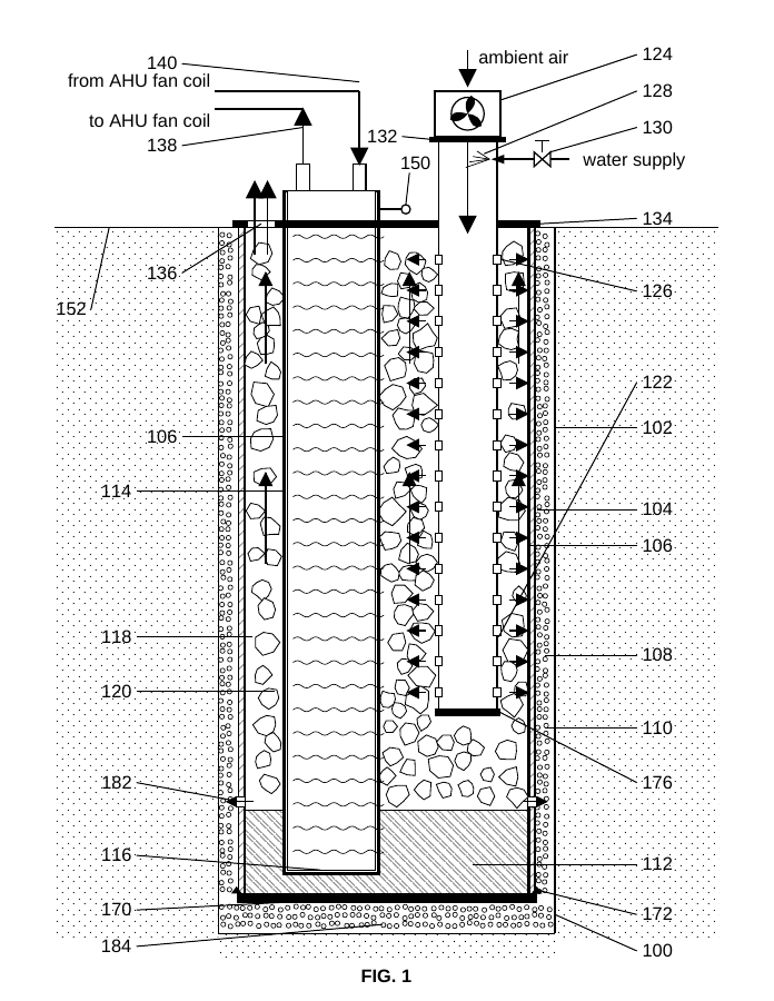
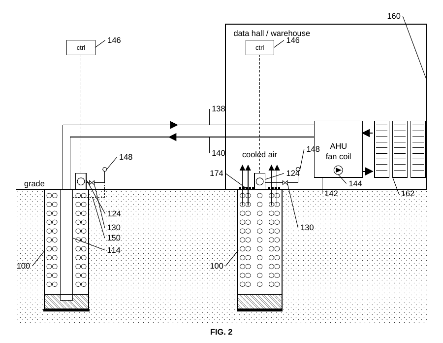
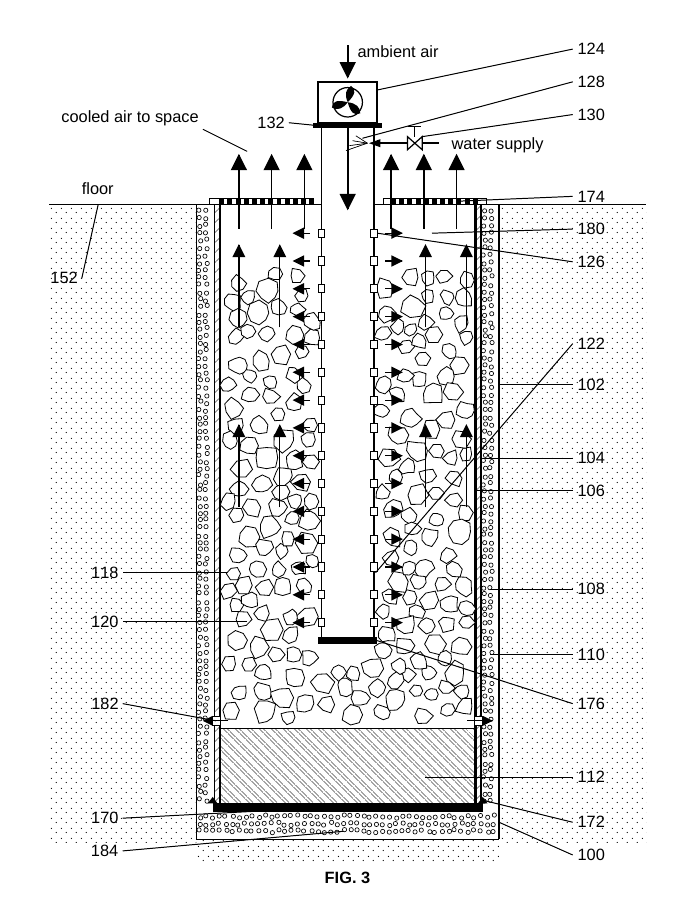
The drawings depict a below-grade assembly, ambient-air and water-supply paths, and arrangements serving an air-handling fan coil or conditioned space. They are presented as supplied drawings; performance and development status should be confirmed with Footprint Engineering.